slope generator module
https://kassu2000.blogspot.com/2016/04/slope-generator.html
Loop stability (update March 2019)
The basic slew limiter circuits shown above has stability issues at some settings, causing the output voltage of U1B to oscillate. While these oscillations are quite small at the final output, it is a good idea to fix them.
Slew Limiter
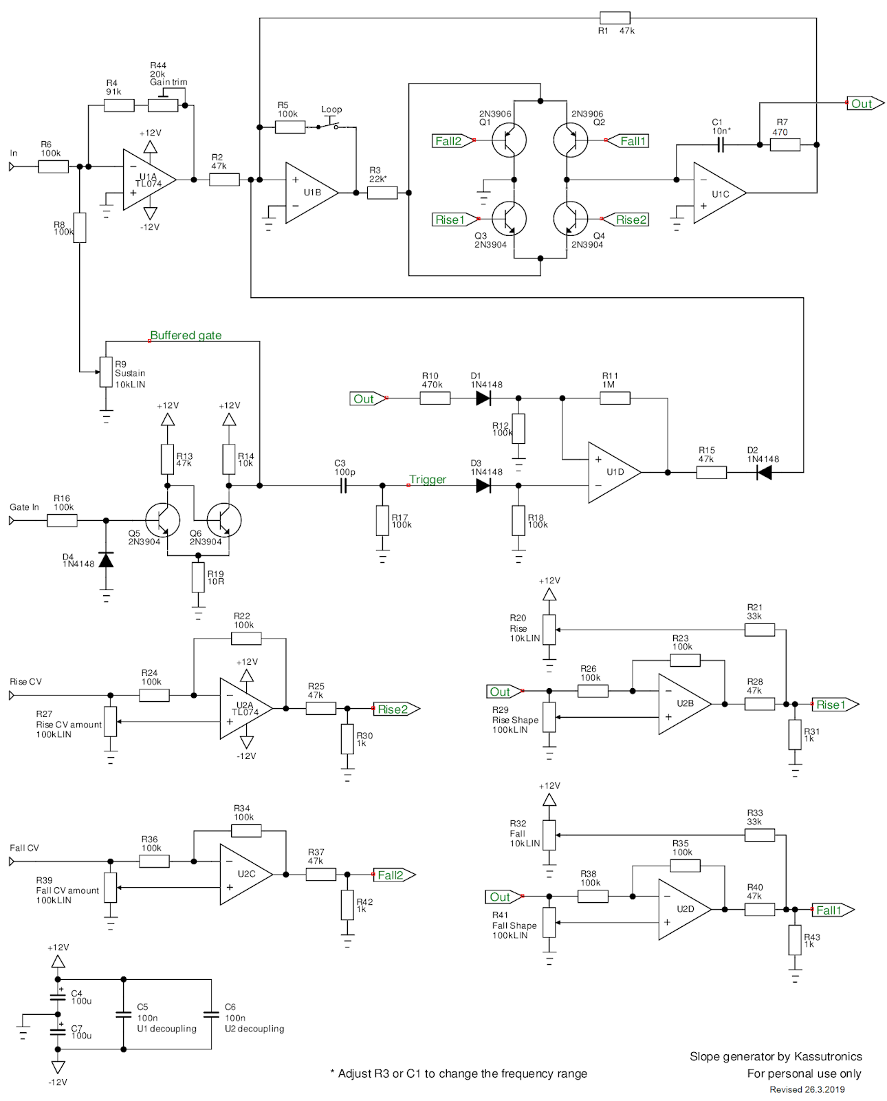
The slew limiter can be stabilized with a small resistance in series with the timing capacitor C1. This is shown as resistor R7 in the complete circuit below. The value of R7 can be adjusted if needed, in my tests 470 Ohm seemed to work well. Note that the output is tapped off between C1 and R7, such that the voltage drop over R7 does not affect the slew limiter output.
Envelope
The gate input is processed by a Schmitt trigger, Q5 + Q6 and surrounding components, which turns any input signal (at least ~ 1V) into a well-defined gate. This gate is turned into a short trigger pulse by C3/R17.
The envelope timing is controlled by U1D, which acts as a set/reset latch. The latch is "set" by the trigger pulse. This makes the output of U1D go negative, and this negative voltage is fed to the slew limiter, which then starts to ramp up the main output. Feedback resistor R11 keeps the latch "set" even when the trigger has ended. The slew output continues to rise, but when it reaches about 5V it "resets" the latch via R10 and D1. The slew limiter is now free to go downwards again, completing the Attack/Release envelope circuit. The Sustain function is created by feeding part of the gate signal to the slew input through R8.
Loop function
The loop function is very simple: it switches in a positive feedback path R5 around U1B. This makes that the slew limiter wants to continue in the direction it is going. It continues until the output reaches about +5V or -5V, and the negative feedback via R1 becomes stronger than the positive feedback through R5. Then it flips around, and loops eternally in the +/-5V range.
Control voltage processing
U2 forms four attenuverter circuits, that can attenuate as well as invert a CV signal with a single knob. U1A and U1C are for the rise and fall CV inputs, respectively, and these are scaled down and fed to the Rise2 and Fall2 points in the slew limiter. U1B and U1D are for the shape controls. These work by feeding a portion of the output back to the voltage control points Rise1 and Fall1, either directly or inverted. This creates, depending on the setting of the shape potentiometer, either exponentially growing or exponentially decaying outputs. Exponential decay is like the RC charging/discharging curve found in many traditional ADSRs (including mine), while exponential growth gives signals that start off slowly, but then end with a fast spike. The manual settings for rise and fall time are also combined to the Rise1 and Fall1 points.
Other details and modification ideas
- The frequency range can be adjusted by changing R3 and/or C1. Bigger values give slower response.
- The output of U1B could be used as a basis for logic signals that indicate when the output is rising (U1B at -12V), falling (U1B at +12V) or in steady state (U1B at about 0V). Especially the falling option is easy to implement and useful: the module can then be a pulse delay and shaper, where rise time sets the delay and fall time sets the pulse length.
- It would be useful to add an LED to indicate what the output is doing. A bicolor LED (two LEDs in one package) is most suitable, for example with an opamp driver circuit as shown in this LFO, or simply with a series resistor (value 2.2k - 10k depending on desired brightness) directly from Raw out to ground.