DIY Power Supply
creation date: 2025-02-28 14:03
modification date: 2025-02-28 14:03
to update:
github files for protoboard
link to hex standoffs
talk about hex standoffs more
link to aliexpress protoboard
Building the Power Supply
My friend Paul aka awsumtronix have been exchanging DIY modules for a few years at this point and a few months ago he gave me a DIY eurorack power supply kit that he designed. I didn'td have a reason to build this power supply kit until recently when I wanted to work on my Daisy Patch.init() module with my laptop at my kitchen table. I currently am working on a massive eurorack ( Building the Ultimate Eurorack Case) case that is not easy to move into my kitchen. Needless to say most of my modules live there so I've 3d printed a little 42hp skiff with a 4hp insert on the back to put this power supply. Ideally I'd like to be able to have my portable USB-C power bank to supply this thing but we'll get into that.
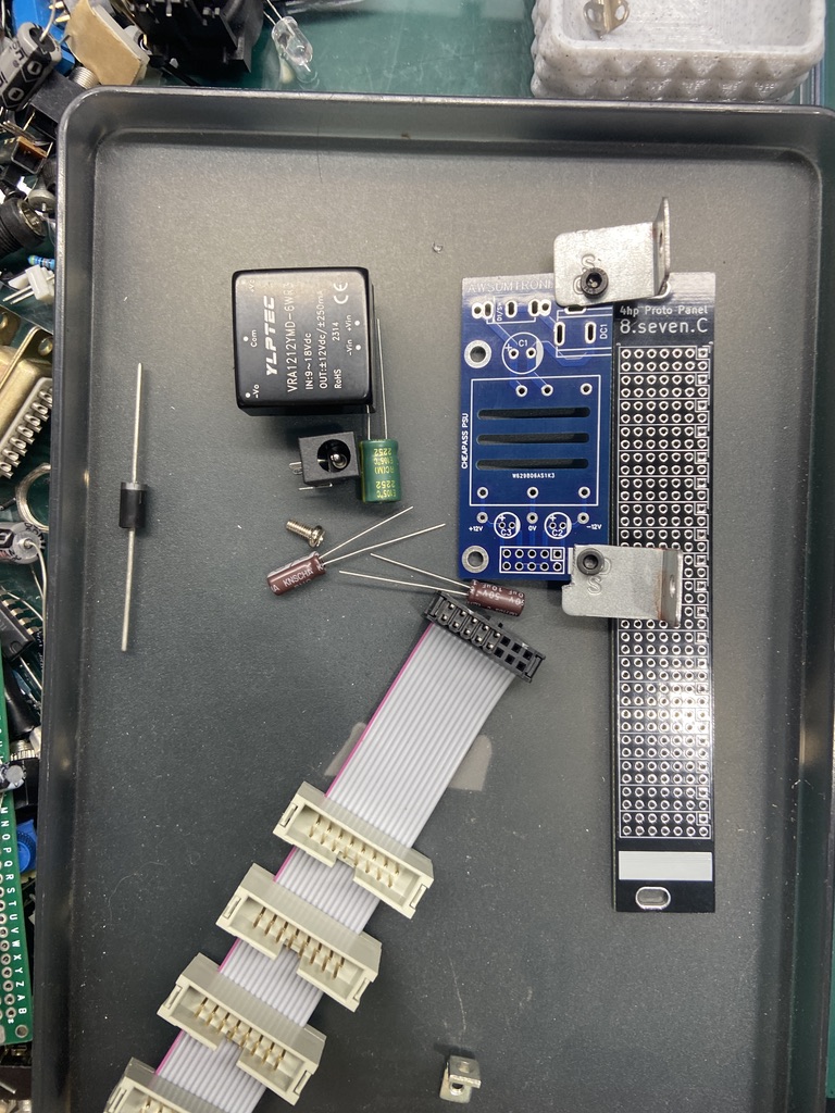
Parts / Components
It was pretty bare bones:
- dc-dc converter
- 2.1mm barrel power jack
- 10pin (2x5) power pin header
- a diode and come filter caps
- PC Mounted SPST Toggle Power Switch
- PCB
- Everything else you see in this doc was sourced elsewhere (mostly my parts bins).
I had a 4hp prototype pcb panel ready to go for this project as I ordered 20 of them a few months ago. (put them up on GitHub and put the link here)
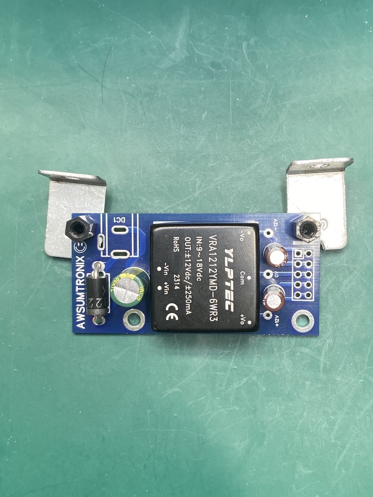
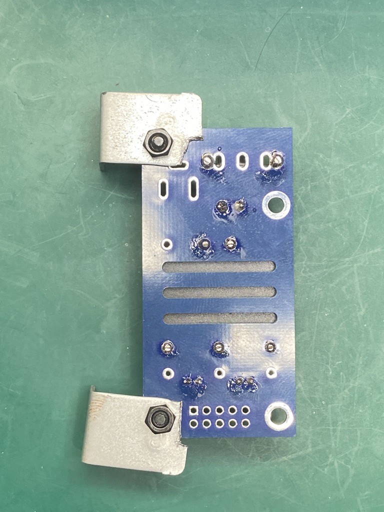
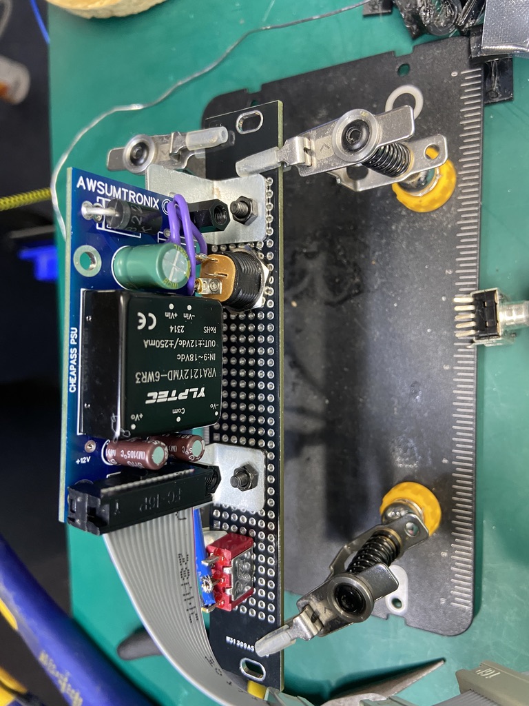
Being the collector that I am, I have many small bins of random stuff. One of which is a bin of metal parts. The right angle brackets (seen below) were salvaged from some extra furniture parts (i always keep the extra parts for stuff like this) to mount the PCB behind the front panel.
As for power distribution: I have stupid amount of ribbon cables (probably 2000 that I got a deeeeeep discount) so I though flying bus power was the right solution for this considering the dc-dc converter can only supply 250mA. So I ordered some of these male snap on connectors (10pcs 2.54mm Pitch 16 Pin Male Straight IDC Box Header Connector For 1.27mm Pitch Flat cable DC3) to make flying bus power cables (seen below).
First Dry Fit
It was at this point that I realized that I wasn't going to be able to use the original 2.1mm barrel power connector that came with the kit. Luckily I have about a million other 2.1mm barrel connectors with solder lugs from my days of making pedals. I also made the decision to go with a different toggle switch that can access from the front panel considering the toggle switch that came with the kit is meant to be mounted to the pcb. It will be inaccessible when I have the power supply in the skiff. Naturally an ON-ON SPST Mini Toggle Switch will do the trick.
Populating the PCB
After getting the lay of the land and a better idea of what extra parts I needed, I started soldering the components.
- DC-DC converter
- Diode
- Power filter caps
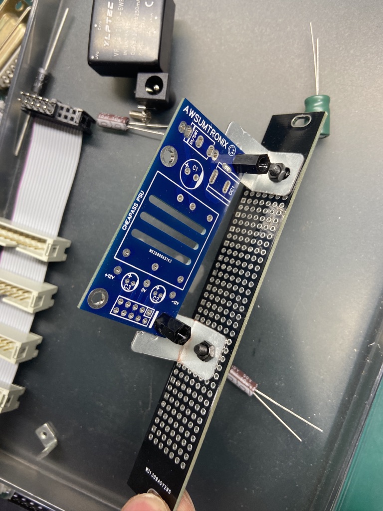
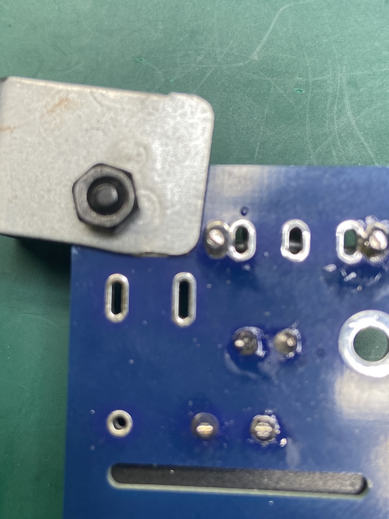
Mounting Bracket Considerations
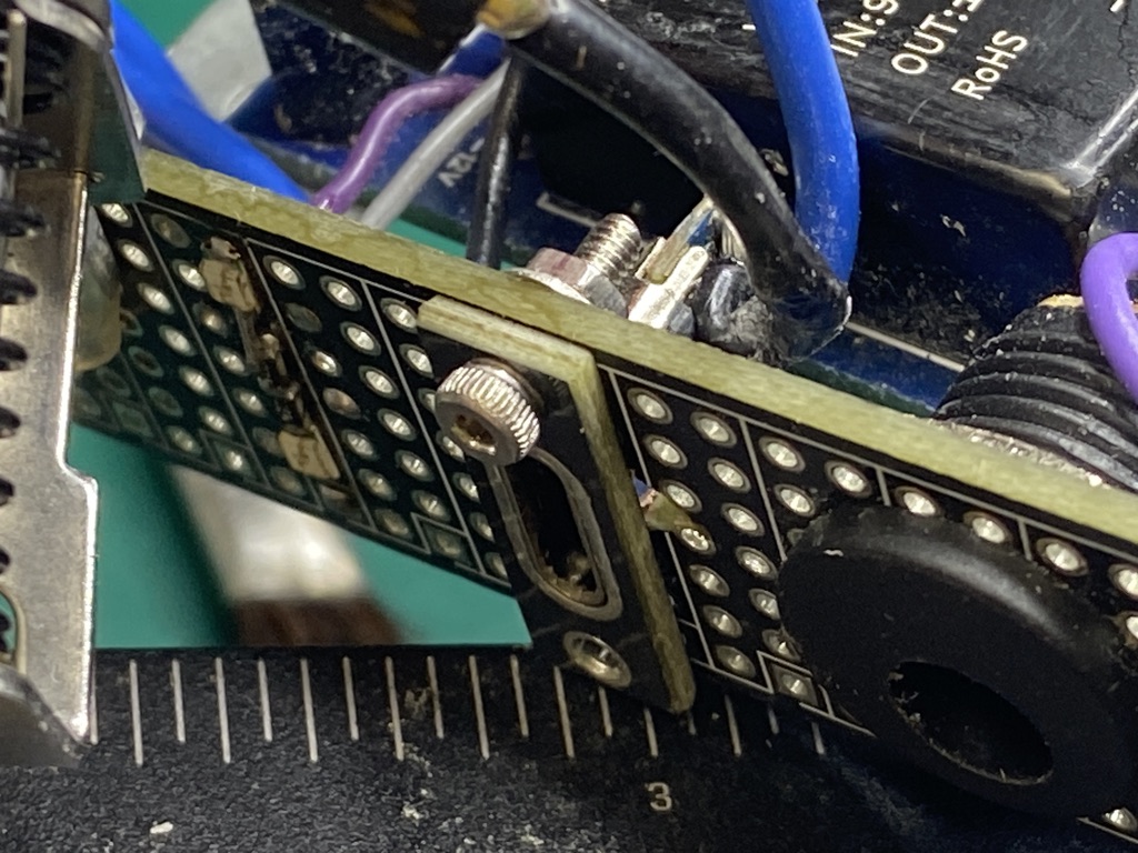
It was at this point that I realized that the metal bracket was close to that diode pad for comfort. Something that a pair of snips cant handle…
Snipping off the corner of the bracket
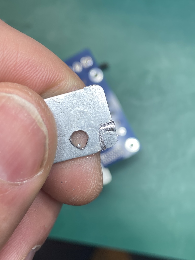
"Clearance is clearance" as they say in the machining world.
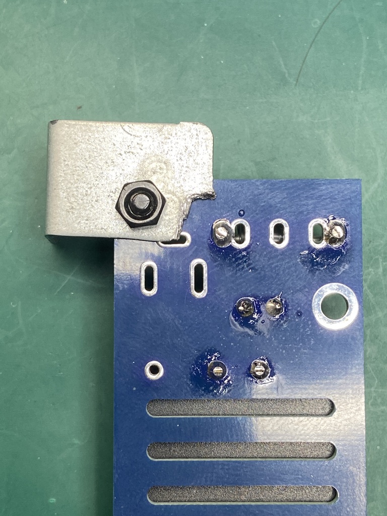
It then came to my attention that the other mounting bracket needed a little TLC as well. Shorting the power pins would be a fun way to make garbage.
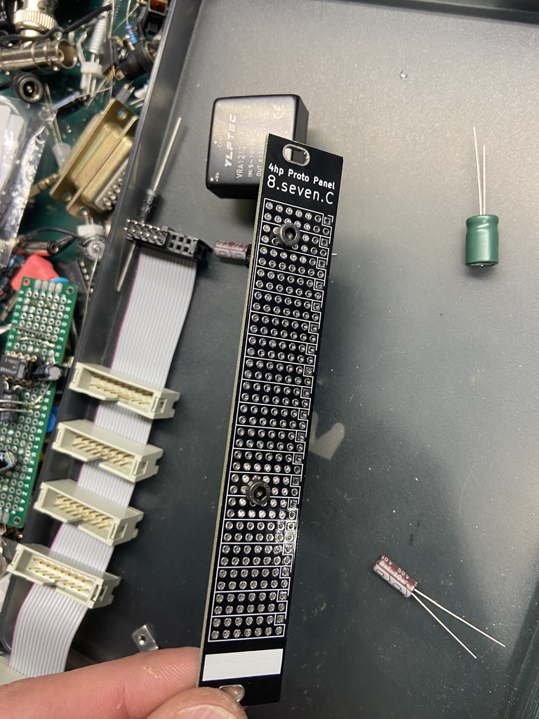
The Front Panel
Now that the mounting brackets are situated on the PCB. I needed to drill some small holes to mount the other side to the back of the faceplate. As I had mentioned earlier in this doc, I had ordered a bunch of these 4hp prototype panels a few months ago. What I didn't mention was that I designed these in Kicad have them up on GitHub for download. Feel free to use them for your next eurorack project.
Also pictured below is the completed flying power bus ribbon cable.
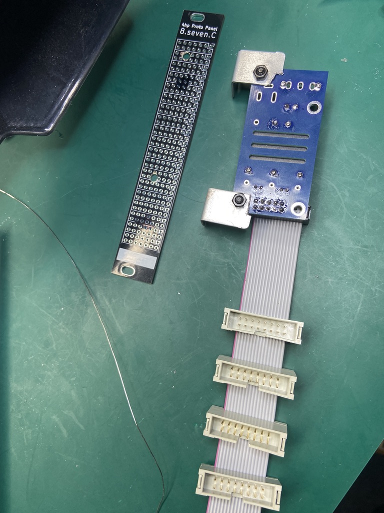
'Flying' Power Bus Ribbon Cable
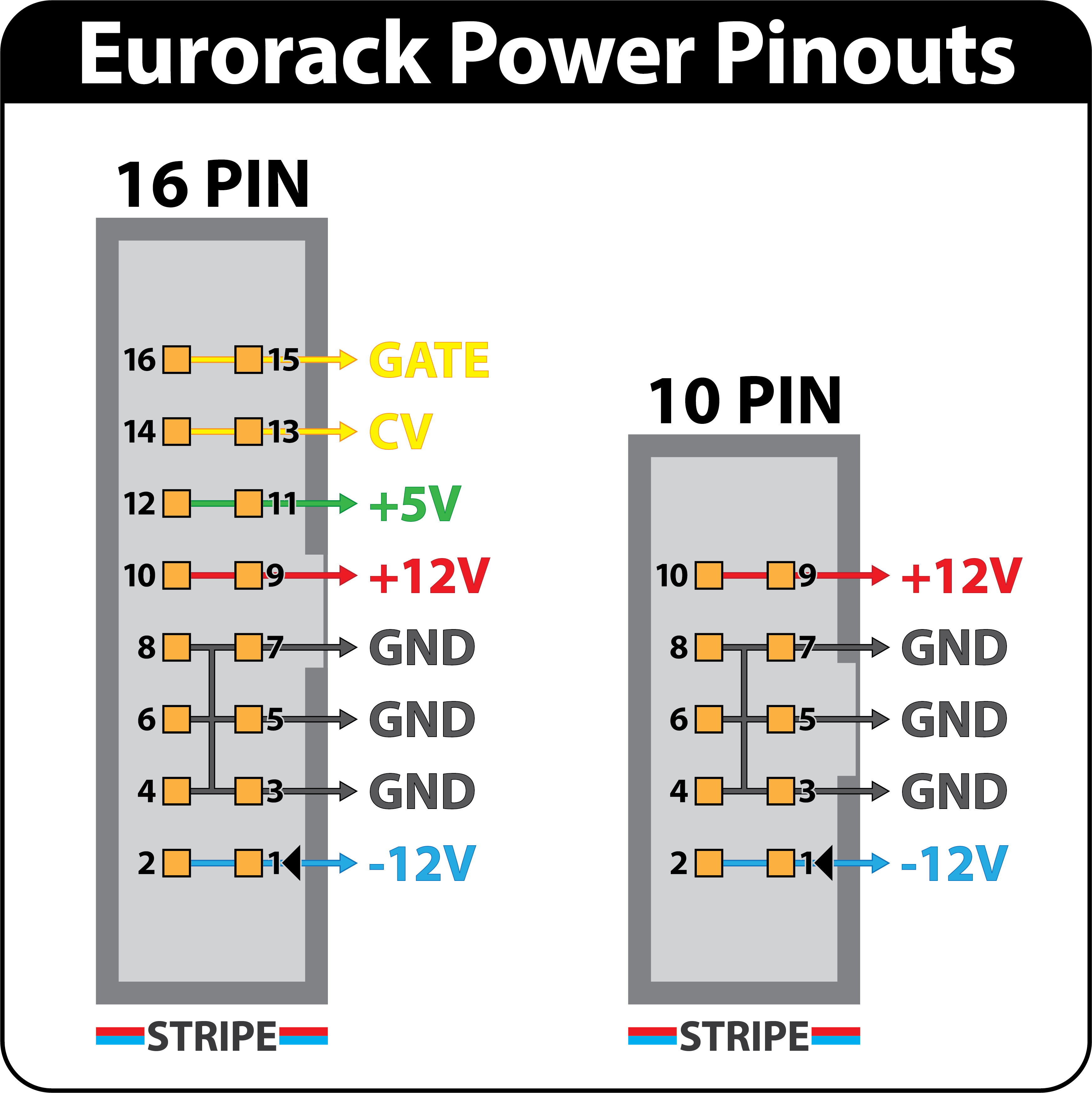
Due to the fact that the DC-DC converter voltage output is +12V / -12V, there is no 5V rail. So the pinout Paul chose for the supply only has 10 pins, not 16. I often find myself referring to this image for eurorack power pinout, but at this point I've memorized red strip = -12V 😅 .
Eurorack Power Pinout
The ribbon cables that I have a stockpile of, have to be seated offset to omit those extra 6 pins (seen at the bottom right corner of the pcb below). The mounting screw for that hole also needed to be DNP (do not populate) in order for the power pin header housing to fit.
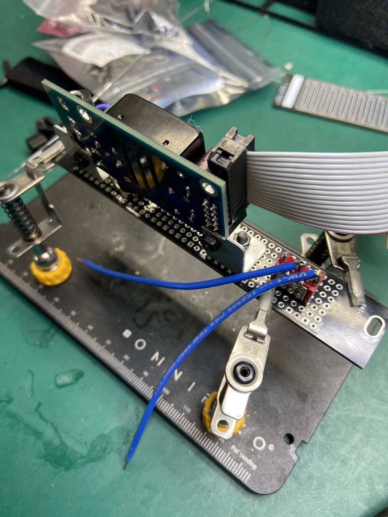
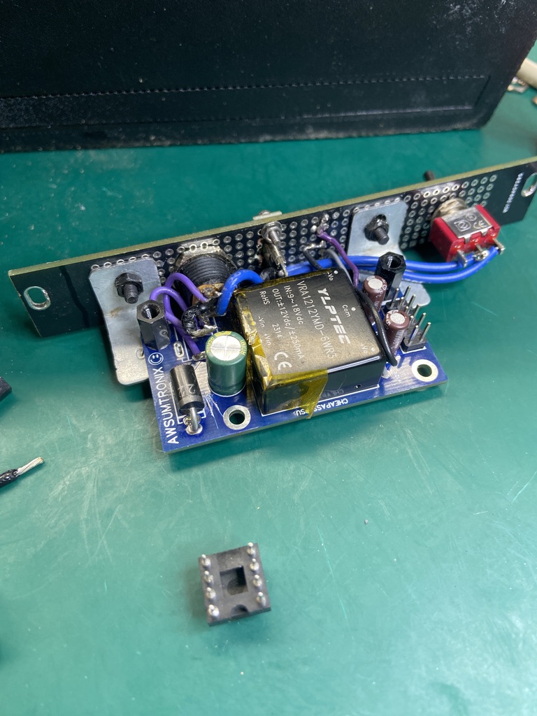
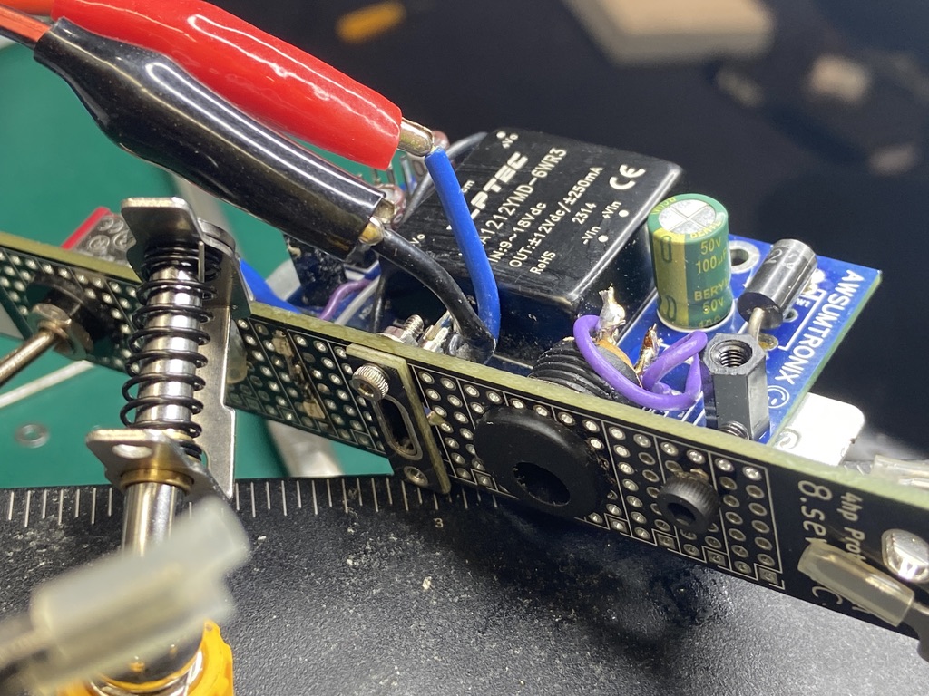
Power Toggle Switch
As mentioned earlier, I used an SPST ON-ON toggle switch (that little red guy at the bottom) to toggle the power on an off. Works like a charm.
What I've learned so far…
After wiring everything up and soldering it all together, I realized I made a mistake and wired the power jack the wrong way. Whoops! All good though, I just reversed the wires and we were smooth sailing. So I had thought… Wiring up the power jack to accept center negative +9VDC from my one spot was no problem. The power supply was reading +12V / -12V . Everything is kosher. I go to put it in the skiff and my modules power up! Sweet! I mess around for 20-30 mins and go to turn it off and it doesn't turn off. I think to myself "hmm maybe I wired the switch wrong". I take it all apart and realized that this toggle switch was not designed the say the way that the toggle switch that came with the kit was. I ended up desoldering the switch, cutting a trace and soldering the wire to a pad on the input filter cap. Just like that, the toggle switch was working.
LEDs and USB-C Power
I decided to mount some 0805 red LEDs on the front panel to give me a power good indication for both +12V and -12V. Now here is where things get tricky. Remember how I mentioned that the DC-DC converter accepts 9VDC? (well technically 9-18VDC). Here is what my dumb ass thought: "Oh, I'll just wire up a 5V USB-C Power jack and call it a day" (hockey game buzzer sound ERR). Wrong. Here is what I intend to do: I will add a MAX1044 voltage doubler to the output of this 5V supply, making it 10V. The only concern I have is that it may not be able to handle the current so I may need a current amplifier if thats the case. Either way, its a plan.
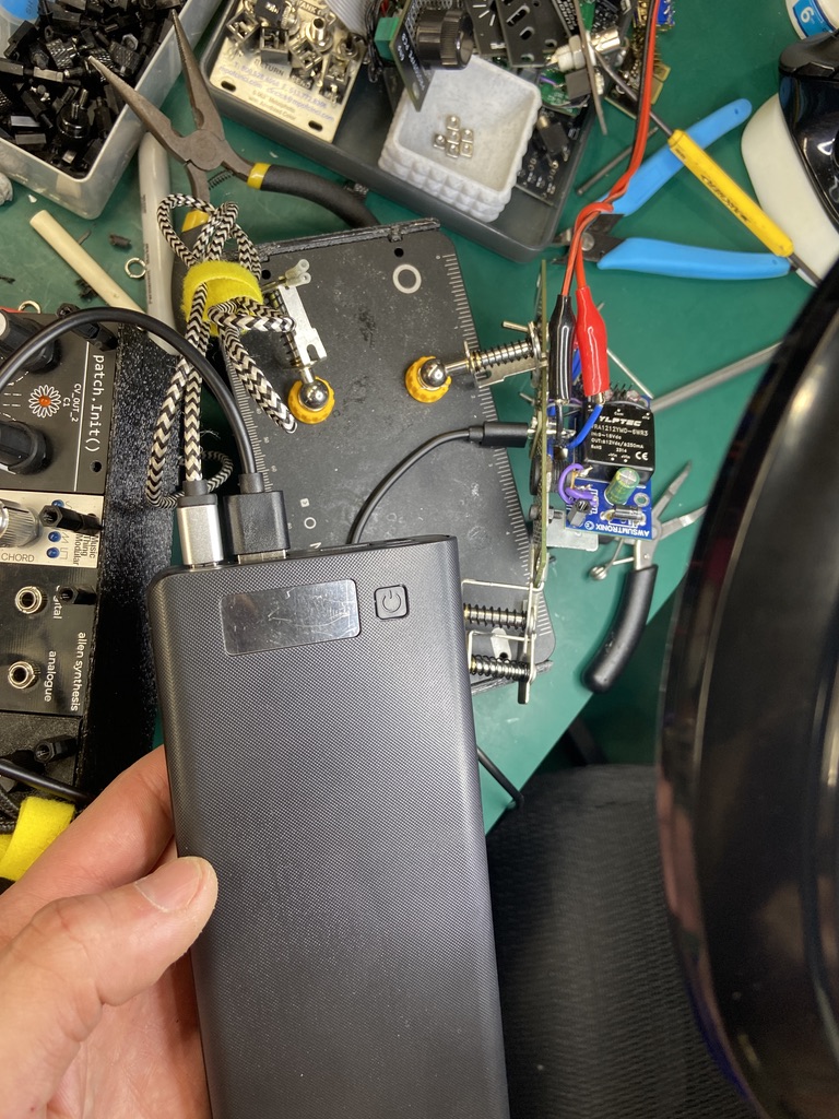
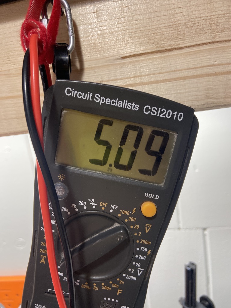
Confirming that the USB-C Power does in fact give me 5V. Yay!
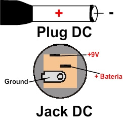
Power Jack Normalizing
There needs to be a way for the power jack to know which should supply power. If both power jacks are drawing from 2 different power supplies, magic smoke will fill the air. Conveniently, these 2.1mm barrel jacks have a normalizing pin that is meant for 9V batteries. So when the barrel jack is connected, the battery supply is cut off. That is exactly what I am going to implement here. The 5V USB-C (Converted to 10V) will be the "battery" and the 9V DC supply will remain the same. This way, the 9V supply has priority over the USB-C power bank. Cool!
Im not proud of the soldering on this build. It is what it is. A prototype! Im figuring things out as I go.